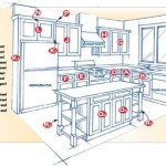
How to Draw Kitchen Cabinet Elevations
Kitchen cabinet elevations are essential for visualizing the final look of a kitchen remodel or new construction. They provide detailed depictions of each cabinet unit, showing dimensions, styles, and features. Accurate elevations are crucial for effective communication between designers, contractors, and homeowners, ensuring the finished product matches the intended design.
Before beginning to draw, gather the necessary tools. These include a pencil, eraser, ruler, measuring tape, and drawing paper. Graph paper is highly recommended for maintaining consistent scale and accurate measurements. CAD software can also be utilized for professional-grade drawings, offering greater precision and the ability to easily make revisions.
The first step involves accurate measurement of the existing kitchen space or the planned layout. Record the length, width, and height of the walls where cabinets will be installed. Note the locations of windows, doors, appliances, and utilities like plumbing and electrical outlets. These measurements form the foundation for accurate elevations.
Start by drawing a baseline representing the floor. Use a consistent scale, such as 1/4 inch equals 1 foot, to ensure the drawing remains proportional to the actual kitchen dimensions. Mark the locations of windows, doors, and appliances along the baseline according to the measurements taken.
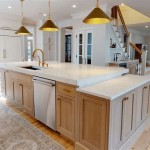
Next, draw the individual cabinet units. Represent each cabinet with a rectangle, adhering to the chosen scale. Standard cabinet depths are typically 12 inches for wall cabinets and 24 inches for base cabinets. Heights vary depending on the specific design, but common heights are 30 inches for base cabinets and 36 inches for wall cabinets. Indicate the height of the cabinets from the baseline to represent their position accurately.
Within each cabinet rectangle, add details such as door and drawer fronts. Use lighter lines to indicate interior shelves and dividers. Clearly label each cabinet with its dimensions and designated purpose, such as "sink base cabinet" or "corner wall cabinet." This clarity minimizes potential confusion during installation.
Indicate the hardware chosen for the cabinets, such as knobs, pulls, or handles. Represent these elements with simple shapes and label them appropriately. Include details like crown molding, toe kicks, and decorative panels if they are part of the design. These details enhance the realism of the elevations and aid in visualizing the finished product.
For wall cabinets, indicate the distance between the bottom of the cabinet and the countertop. This measurement is crucial for ensuring proper functionality and clearance for countertop appliances. Typically, the distance is between 15 and 18 inches.
Maintain consistent line weights throughout the drawing. Use thicker lines for the outlines of the cabinets and thinner lines for interior details and annotations. This visual hierarchy improves readability and makes the drawing easier to understand.
Add dimensions to the drawing. Include overall dimensions of the wall runs, as well as individual cabinet dimensions. Clearly mark the height of the cabinets, the distance between cabinets, and the distance from cabinets to windows, doors, and appliances.
Annotate the drawing with any relevant notes or specifications. This might include details about the cabinet construction materials, finishes, or special features. Clearly communicate any specific installation instructions or requirements.
Create separate elevations for each wall of the kitchen. This provides a comprehensive view of the entire design. Label each elevation clearly, indicating the corresponding wall. For example, "North Wall Elevation" or "East Wall Elevation." Maintain consistent scale and style across all elevations for a unified presentation.
Review the completed drawings thoroughly for accuracy and completeness. Double-check all measurements and ensure that the drawings accurately reflect the desired kitchen design. Any errors or omissions at this stage can lead to costly mistakes during construction.
Consider using different line types to represent different materials or components. For example, dashed lines might indicate hidden lines or concealed features. Different line weights can also be used to distinguish between different types of cabinets or materials.
Adding shading or rendering to the elevations can enhance their visual appeal and provide a more realistic representation of the finished kitchen. However, this is not essential for communicating the necessary information to contractors and installers.
Once the drawings are complete, distribute copies to all relevant parties, including the homeowner, contractor, and cabinet supplier. This ensures that everyone is working from the same information and minimizes the potential for miscommunication or errors.

Dk Studio

21 Kitchen Drawings Plan Elevation Section Ideas Drawing Plans Layout

Design Your Kitchen Aplus Interior Remodeling 949 458 2108

Pin By Tad Braner On Building Huff N Puff All U Want Kitchen Layout Plans Elevation Drawing

How We Measure For Kitchen Cabinets Model Remodel

How Hard Is It To Install Kitchen Cabinets The Exciting Part Of Our Diy Reno Create Enjoy

Creating A Cabinet Detail Detailing Shaker

Graphic Standards For Architectural Cabinetry Life Of An Architect

Dynamic Kitchen Cabinet Elevation Cad Drawing Details Dwg File Cadbull

Specification Edgewood Cabinetry
Related Posts