Kitchen Cabinet Section Detail CAD: A Comprehensive Guide
The creation of detailed and accurate drawings is crucial in the design and construction of kitchen cabinets. Section detail CAD drawings provide a magnified, cross-sectional view of cabinet components, illustrating their construction, materials, and relationships to adjacent elements. These drawings are essential for communication between designers, manufacturers, and installers, ensuring that cabinets are fabricated and installed according to the specified design intent. A clear understanding of kitchen cabinet section detail CAD and its associated keywords is fundamental for professionals in the cabinetry and construction industries.
Section detail drawings go beyond standard plan and elevation views by providing close-up representations of specific areas within a cabinet. This level of detail is necessary to accurately portray complex joinery, hardware placement, internal components, and the integration of cabinets with surrounding architectural features, such as walls, floors, and countertops. The use of CAD (Computer-Aided Design) software streamlines the creation and modification of these details, enabling designers to produce precise and comprehensive drawings that minimize errors and improve overall project efficiency.
The accuracy of section detail CAD drawings is paramount for a successful kitchen cabinet project. Dimensional inaccuracies or omissions can lead to costly rework, delays in project schedules, and potential structural or functional issues. Therefore, it’s critical that the drawings are meticulously prepared, adhering to industry standards and incorporating all relevant information necessary for the manufacturing and installation processes. Effective communication, facilitated by well-documented section detail drawings, contributes significantly to the successful execution of kitchen cabinet projects of all scales.
Key Elements Illustrated in Section Detail CAD Drawings
Kitchen cabinet section detail CAD drawings are comprehensive documents that illustrate various aspects of cabinet construction. These drawings are not simply aesthetic representations; they are technical documents intended to guide the manufacturing and installation process. Several key elements are consistently represented:
Cabinet Box Construction: This includes details about the materials used for the cabinet sides, top, bottom, and back. Section details often show the thickness of the materials, the type of joinery used to connect them (e.g., dadoes, rabbets, screws, dowels), and the placement of any internal shelving or dividers. The type of material, whether it be plywood, particleboard, or solid wood, is clearly indicated, along with its specific grade and finish.
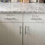
Door and Drawer Details: Section details illustrate the construction of cabinet doors and drawers, including the materials used for the frame and panel, the type of joinery used to assemble them, and the hardware used for hinges, pulls, and knobs. Drawings will often illustrate the profile of the door style, whether it be a raised panel, a shaker style, or a slab door, as well as the overlay of the door and drawer front onto the cabinet frame (full overlay, partial overlay, or inset).
Hardware and Fittings: Precise locations and specifications for hinges, drawer slides, knobs, pulls, and other hardware are crucial. Section detail drawings show the type of hardware, its dimensions, and how it is attached to the cabinet. This also includes specialized hardware like soft-close mechanisms, pull-out shelves, and integrated lighting systems. Correct specification and placement ensure smooth operation and longevity of the cabinets.
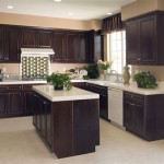
Countertop Interface: The section detail clearly illustrates how the countertop integrates with the cabinets. This includes the type of countertop material (e.g., granite, quartz, laminate), its thickness, and the method of attachment to the cabinet base. The drawing should also indicate if any supports are required for the countertop overhang and how they are integrated into the cabinet design.
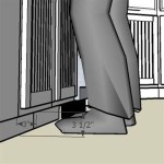
Wall and Floor Interfaces: The detail shows how the cabinet interfaces with the walls and floors. This includes any shimming needed to level the cabinets, the method of securing the cabinets to the wall (e.g., screws, cleats), and the type of toe kick used. The relationship of trim, such as scribe molding, to the wall is also represented, compensating for any irregularities in the wall surface.
Common Kitchen Cabinet Section Detail CAD Keywords
Using the correct keywords when searching for or creating kitchen cabinet section detail CAD drawings is crucial for efficient information retrieval and accurate communication. Several key terms are commonly used and associated with different aspects of cabinet construction and design:
"Section Cut": This refers to the act of slicing through a three-dimensional object to reveal its internal structure. In CAD, a "section cut" creates a two-dimensional representation of this cut, showcasing the various layers and components within the object.
"Cabinet Carcass": This term refers to the main structural body of the cabinet, excluding doors, drawers, and hardware. Section details of the cabinet carcass will focus on the materials, joinery, and internal components of the cabinet box.
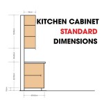
"Toe Kick Detail": The toe kick is the recessed area at the base of a cabinet that allows for comfortable standing space. Section details of the toe kick will show its height, depth, and construction method, including the material used and how it is attached to the cabinet carcass.
"Face Frame Detail": A face frame is a wooden frame attached to the front of the cabinet carcass, providing structural support and a decorative element. Section details will show the dimensions of the frame members, the type of wood used, and the method of attachment to the cabinet carcass.
"Frameless Construction": Also known as "European-style" cabinets, frameless cabinets lack a face frame. Section details will focus on the exposed edges of the cabinet carcass and the hardware used to attach doors and drawers directly to the cabinet sides.
"Door Overlay": This refers to the amount that the cabinet door overlaps the cabinet frame or carcass. Common types of door overlay include full overlay, partial overlay, and inset. Section details will clearly show the amount of overlay and the type of hinges used to achieve it.
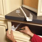
"Drawer Slide Detail": Drawer slides are the mechanisms that allow drawers to open and close smoothly. Section details will show the type of drawer slide (e.g., ball-bearing, soft-close), its load capacity, and its method of attachment to the drawer box and cabinet carcass.
"Hinge Detail": Hinges are the hardware that allows cabinet doors to swing open and closed. Section details will show the type of hinge (e.g., concealed, surface-mounted), its opening angle, and its method of attachment to the door and cabinet carcass.
"Shelf Detail": This illustrates the material, thickness, and support system used for shelves within the cabinet. Details will specify whether the shelves are adjustable or fixed, and the type of shelf supports used (e.g., shelf pins, cleats).
"Countertop Edge Detail": The profile and material of the countertop edge are detailed in this section. This includes information on the edge treatment (e.g., bullnose, ogee, beveled) and how it is finished and attached to the countertop surface.
Importance of Accuracy and Standardization in Section Detail CAD
The accuracy and standardization of kitchen cabinet section detail CAD drawings are critical for several reasons, contributing significantly to project success and minimizing potential issues throughout the design and construction phases:
Preventing Errors and Rework: Precise and detailed section drawings provide a clear understanding of how all cabinet components fit together, reducing the likelihood of errors during manufacturing and installation. This minimizes costly rework and delays in the project schedule. Ambiguous or inaccurate drawings can lead to misinterpretations by fabricators and installers, resulting in components that do not fit properly or function as intended.
Ensuring Compliance with Codes and Standards: Building codes and industry standards often dictate specific requirements for cabinet construction, materials, and installation. Accurate section details demonstrate compliance with these regulations, ensuring the safety and structural integrity of the kitchen cabinets. This is particularly important in areas subject to seismic activity or other environmental factors that may impact cabinet stability.
Facilitating Communication: Standardized section detail drawings serve as a common language among designers, manufacturers, and installers, fostering clear and effective communication. Consistent use of terminology, dimensions, and symbols ensures that all parties have a shared understanding of the design intent. This reduces the potential for miscommunication and misunderstandings, leading to a smoother and more efficient project workflow.
Optimizing Manufacturing Processes: Detailed section drawings provide manufacturers with the information they need to accurately fabricate cabinet components. This includes precise dimensions, material specifications, and joinery details. By providing this information upfront, manufacturers can optimize their production processes, reduce waste, and ensure that cabinets are built to the required specifications.
Streamlining Installation: Clear and comprehensive section details guide installers in the proper placement and assembly of kitchen cabinets. The drawings show the location of mounting points, hardware, and other critical elements, facilitating a smooth and efficient installation process. This reduces the time required for installation and minimizes the potential for errors or damage to the cabinets.
Supporting Cost Estimation: Accurate section detail drawings provide a basis for accurate cost estimation. By clearly defining the materials, hardware, and labor required for cabinet construction, the drawings enable designers and contractors to develop realistic budgets and avoid unexpected cost overruns. This is particularly important in large-scale projects where even small inaccuracies can have a significant impact on overall project costs.
In conclusion, section detail CAD drawings are essential tools for the design, manufacturing, and installation of kitchen cabinets. Their accuracy, clarity, and standardization are paramount for ensuring project success, minimizing errors, and facilitating effective communication among all stakeholders. By understanding the key elements illustrated in these drawings and utilizing the correct keywords, professionals in the cabinetry and construction industries can leverage the power of CAD to create high-quality, functional, and aesthetically pleasing kitchen spaces.

Drawing Of Kitchen Section In Autocad Open House Plans

Kitchen Cabinet Section Detail

Kitchen Cabinet Detail Dwg For Autocad Designs Cad

Kitchen Furniture In Autocad Cad Free 61 62 Kb Bibliocad

Cad Detail Of Kitchen Dwg Free Blocks

Kitchen And Cabinets Section Detail Drawings

Pantry Counter And Sink Fixing Detail Free Cad Drawing Plan N Design

Cad Detail Drawing Of Kitchen Cabinets By Dashawn Wilson At Coroflot Com

Details Dry Pantry Cabinet Dwg Detail For Autocad Designs Cad

Cabinet Section Drawing Learn Autocad Relationship Diagram